


by David Löschenbrand and Thomas Zemen (AIT)
Massive multiple input multiple output (MIMO) is widely considered as a key enabling technology for 5G. It promises increased spectral efficiency and the mitigation of small-scale fading in rapidly time-varying communication channels through channel hardening due to the large amount of base station antennas. Spectral efficiency is of utmost importance for data-heavy applications. Channel hardening, however, is a key feature for ultra-reliable low latency communication (URLLC) because large fading dips causing loss of possibly safety-critical messages can be avoided. In the project MARCONI we investigate a measurement framework for rapidly time-varying distributed massive MIMO communication channels typically found in vehicular scenarios. With this empirical data we will work on massive MIMO channel models and new transceiver algorithms enabling a constant transmission quality from the base station to the mobile station. We will explore algorithms to enable these properties for the first time for highly time-variant and non-stationary V2I scenarios in both time-division duplex (TDD) and frequency division duplex (FDD) systems. We analyse the measured channel characteristics over time for collocated and distributed receive antenna setups to evaluate the fundamental limits of communication systems in such scenarios. Our results show that antenna placement plays a crucial role for establishing ultra-reliable communication links between cars and infrastructure.
The performance of wireless communication systems is limited on a physical level by the characteristics of the wireless propagation channel. Vehicular scenarios pose a great challenge to communication systems due to the large (relative) velocities, many moving metallic reflectors and low flexibility in antenna placement [1]. The utilisation of massive MIMO communication links for vehicle to infrastructure (V2I) applications in safety-critical scenarios promises reliability and robustness against harsh propagation conditions of vehicular settings through channel hardening [2].
The characterisation of these propagation conditions via measurements lays the foundation for future ultra-reliable low latency communication (URLLC) systems. Due to the rapidly time-varying and non-stationarity behaviour of the channel, common measurement that rely on slowly changing or constant propagation conditions are not applicable for V2I scenarios. To this end, we are developing a fully parallel distributed massive MIMO channel measurement framework capable of characterising numerous vehicular channels with high speed. A custom-built calibration unit facilitates the calibration of the measurement framework in the field. A flexible long distance synchronisation solution allows great variability of the antenna placement under test. Below is an overview of our measurement framework and obtained results.
Channel Measurement Framework
The transmitter node of the presented massive MIMO channel measurement framework consists of a software-defined radio (SDR) covering the anticipated 5G frequency ranges below 6GHz. The highly adaptable SDR is programmed to act as two mobile stations (i.e. Smartphones) with one antenna each transmitting data to a base station. A GPS-enabled Rubidium clock is used for nanosecond precision synchronization to the base station and for localization in space. The setup is powered by an uninterruptible power supply which allows for more than four hours of measurement time without the need of a power outlet. The transmitter node is placed in a small van and transmit antennas as well as GPS antennas for position tracking are mounted on the roof of the van. The transmitter node is thus mobile and can be operated at various speeds and in different propagation scenarios.
The receiver features 32 antennas which operate fully parallel and act as a base station. We group the receive antennas into two nodes with 16 antennas each. These nodes can be arbitrarily positioned in space with a separation of up to 60m to analyse different antenna geometries and their performance. The receiver also uses a Rubidium clock for nanosecond precision synchronization. Figure 1 shows the 32 receive antennas of the measurement framework as well as the SDRs (that sample the received signal), the calibration unit and the control computer.
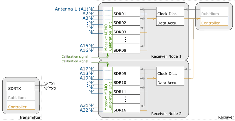
Figure 1: Base station with 32 receive antennas in two nodes (left and right).
A custom built massive MIMO calibration unit is integrated in the measurement framework to ensure fast and reliable calibration. By doing so, the effects of the measurement equipment is factored out and only the effects of the wireless propagation channel remain.
Channel Measurement, Analysis and Results
Vehicular wireless channels exhibit rapidly time-varying behaviour and non-stationary statistics [3]. It is thus crucial to measure the channel repeatedly in time to capture even the slightest variations. We use a broadband signal similar to the ones used in current wireless standards at a carrier frequency of 3. 5GHz (reserved for 5G usage) to capture the channel characteristic over time. The broadband signal is transmitted and received 1,000 times per second to capture the time-varying wireless propagation channel sufficiently often for further analysis.
To analyse the time-variant characteristics of vehicular channels for a given transmitter and receiver, we revert to the time-variant power delay profile (PDP) and the time-variant Doppler spectral density (DSD). The PDP indicates the signal strength arriving at the receiver with a given delay (or, accordingly, with a given distance). The DSD indicates the relative velocities of scattering objects and how much signal strenght is contributed by a scatterer at a given velocity. Since the transmitter and the surroundings move over time, the PDP and DSD also change over time, hence the fading process is non-stationary.
Figure 2 shows the PDP for the transmitter moving away from the receiver, thus increasing their distance and therefore the delay of the transmission. There is a strong line of sight (LOS) component present and the urban environment creates rich scattering with various delay values. Well reflecting and large scattering objects create continuous traces in the PDP plot with changing delay over time. Figure 3 shows the DSD for the same scenario. The departing transmitter creates a strong negative Doppler component. It passes numerous scattering objects, which appear as traces from positive to negative Doppler values.
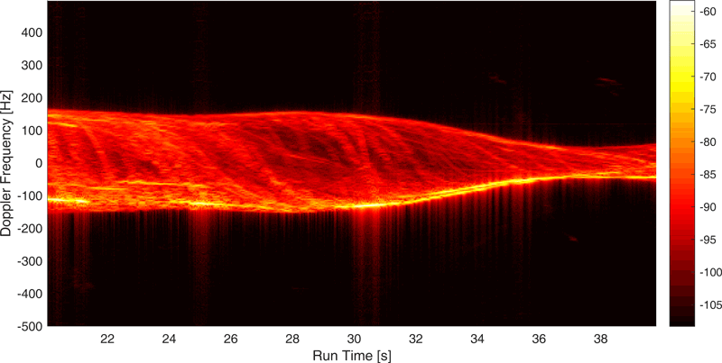
Figure 2: Power delay profile (PDP) for one transmitter-receiver pair for a duration of 20s. The PDP shows a rich scattering environment with a strong line of sight (LOS) path, a second strong path with a delay of 120ns from 32s-40s and various additional multipath components.
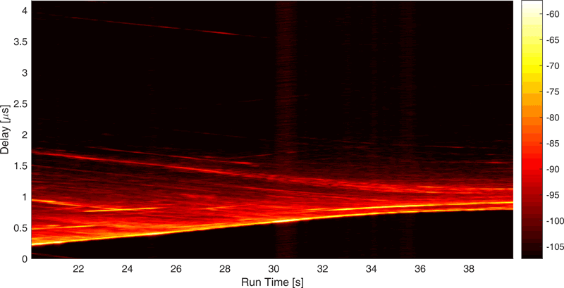
Figure 3: Doppler spectral density (DSD) of one transmitter-receiver pair for a duration of 20s. The DSD shows a strong component with increasing negative Doppler shift. The transmitter is moving away from the receiver, approaching a crossing with ~ 40km/h and decelerating before turning right.
Further analysis, considering all 32 base station receivers and two mobile station transmitters, show the large influence of base station antenna placement on the potential performance of 5G massive MIMO communication systems [4]. Obtaining those results is only possible with a highly flexible distributed measurement framework as presented above. It sparks numerous exiting research questions which are to be addressed for fully leveraging the potential of URLLC systems in 5G.
References:
[1] C. F. Mecklenbräuker, et al.: “Vehicular channel characterization and its implications for wireless system design and performance,” Proceedings of the IEEE, vol. 99, no. 7, pp. 1189–1212, 2011.
[2] T. L. Marzetta, “Noncooperative cellular wireless with unlimited numbers of base station antennas,” IEEE Transactions on Wireless Communications, vol. 9, no. 11, pp. 3590–3600, 2010.
[3] L. Bernadó, et al.: “Delay and Doppler Spreads of Non-Stationary Vehicular Channels for Safety Relevant Scenarios”, IEEE Transactions on Vehicular Technology, vol. 63, no. 1, pp. 82–93, 2014. [Online]. http://arxiv.org/abs/1305.3376
[4] D. Löschenbrand, et al: “Distributed massive MIMO channel measurements in urban vehicular scenario,” in 13th European Conference on Antennas and Propagation (EuCAP), 2019.
Please contact:
David Löschenbrand
Austrian Institute of Technology (AIT), Austria
+43 664 8251089
Thomas Zemen
Austrian Institute of Technology (AIT), Austria
+43 664 88390738

