


by Klaus Wolf and Pascal Bayrasy
The Fraunhofer Institute SCAI has developed an application-independent interface for the coupling of different simulation codes, known as MpCCI (Mesh-based parallel Code Coupling Interface). The MpCCI interface has been accepted as a de facto standard for a neutral and vendor-independent coupling interface. Currently MpCCI supports Abaqus (© Simulia), Ansys (© Ansys Inc), Flowmaster, (© Flowmaster Ltd), Fluent and Icepak (© Ansys Inc), FineHexa and FineTurbo (© Numeca Intl), Flux3D (© Cedrat SA), MD.Nastran and MSC.Marc (© MSC Software Corp), Permas (© Intes GmbH), STAR-CD and STAR-CCM (© CD adapco), and RadTherm (© TAI). An open programming interface has been widely used to adapt customer internal codes as well as public research codes to MpCCI, thus allowing these codes to be coupled with the already supported MpCCI codes.
While typical MpCCI applications are FSI or thermal coupling, the MpCCI System Adaptor is a 1D–3D coupling link which allows the system and network code Flowmaster to co-simulate with full 3D CFD applications; combinations of 1D Flowmaster with 3D CSM (Computational Structural Mechanics) models are under preparation. This generic 1D-3D solution has been developed in order to understand how various simulation models interact with each other and what sort of impact each subsystem has on the overall system performance.
The MpCCI coupling interface combines the speed and robustness of 1D system modelling with the complexity of 3D CFD, enabling system codes like Flowmaster V7 to be used for calculations of the entire flow system and a 3D CFD to perform detailed computational calculations. For example, developing a 3D CFD model for an entire system, such as an automotive cooling system, presents significant challenges. Creating the computational models and their meshes may take a long time and the total number of cells required may make the calculations intractable (ie they may take too long, if they can be done at all). By co-simulating 1D with 3D CFD, more realistic boundary conditions and component models can be obtained, providing a deeper understanding of complex engineering systems.
Obviously this MpCCI 1D-3D combination can be used in any case where it is necessary to look at the detailed flows and designs of particular components within networks. For example:
- virtual prototyping of gas turbine blades: CFD to model the interblade cavities, CSM to model the blades and 1D to model the in-blade cooling channels
- engine cooling systems: modelling the cylinder head and cylinder cooling-jacket with CFD and the external cooling circuit with 1D
- fuel systems (1D) coupled with carburettors (3D)
- within engines (or any combustion process): fuel (1D) + air (1D)
- combustion chambers (3D) - exhaust (1D).
A concrete example of the use of MpCCI is provided by Environmental Control Systems (ECS) in aircraft, which are designed to optimize passenger comfort by providing satisfactory cabin pressurization, temperature and humidity control, whilst minimising risks to passenger health from airborne toxins and diseases.
In a first study it was investigated how the cooling load discharge from an ECS system affects the flow behaviour inside a typical mid-size, wide-body aircraft passenger cabin. The investigation uses 1D software Flowmaster to model the cooling pack, cabin air distribution system, and three quarters of the passenger cabin. The centre section of the cabin is modelled using 3D CFD package (Fluent or STAR-CCM), with the co-simulation middleware MpCCI providing coupling adapters to ensure that two-way, bilateral exchange of boundary parameters between the 1D and 3D CFD models gives continuity of mass and momentum transfer.
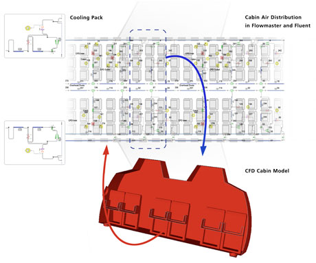
Figure 1: Coupled Simulation of the environmental control systems (ECS) and the cabine internal flows in a mid-size aircraft.
Initially the co-simulation server attempts to procure a converged solution with the 3D CFD model. Resultant boundary pressures and/or flow rates at the interface to the 1D model are exchanged with the 1D model so that it may update its solution (generally a quick process) and exchange and update the boundary conditions for the 3D CFD model. There are two ‘controls’ that the user may use to influence overall convergence behaviour. These are the number of iterations of the 3D solver before a data exchange of boundary conditions, and a relaxation factor which controls the extent of changes between successive calls to the 1D solver. When these parameters are appropriately specified, convergent behaviour is generally observed.
Link: http://www.mpcci.de
Please contact:
Klaus Wolf
Fraunhofer Institute for Algorithms and Scientific Computing (SCAI), Germany
E-mail:
