by Emanuele Carpanzano and Andrea Cataldo
A mechatronic laboratory integrated with an innovative factory has been set up by the Institute of Industrial Technologies and Automation of the Italian Research Council (ITIA-CNR). This infrastructure is strongly exploited for technology-enhanced learning designed for industrial production engineers.
Education courses on automation usually address the development of a control system by starting from the functional specifications, mathematically modelling the control algorithms, and finally running simplified software simulations to verify the correctness of the control system. This contrasts with industrial practice, where the design and implementation of an automation system generally goes from the specifications directly to control code implementation on the specific automation target and to verification in the real industrial plant. The first approach is structured but is not feasible for dealing with the complexity of real-size industrial applications. The second, on the other hand, is unstructured and can thus lead to critical problems during the development of automation solutions. The consequences of these problems are high commissioning times and costs, and final solutions with sub-optimal performance. To bridge the gap between such approaches and to fully support the control system engineer during all the steps required to conceive, study, design, implement and verify an industrial automation system, a dedicated mechatronic laboratory integrated with an innovative RTDI factory has been set up by ITIA-CNR. This piece of infrastructure is strongly exploited for technology-enhanced learning of industrial production engineers.
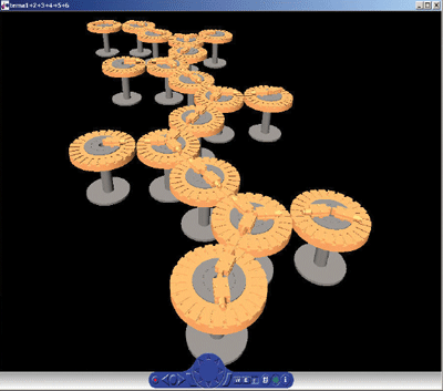
Within education courses the study, design and verification phases of control system development are normally carried out by modelling the control algorithms in specific software environments that also support the numerical simulation for the code verification purposes. The control designer interprets the functional specifications and translates them into mathematical models that are simulated on a PC (see Figure 1). This approach is unsuitable for dealing with large industrial automation systems, because of the excessive complexity of the mathematical models and the computational burden involved in their simulation. Moreover, the implemented control system consists of a formalization of the control strategies, using the formalisms available in the simulation environment. Such a control representation, even if tested, cannot be run on the industrial target, and a relevant effort is therefore necessary to translate the control algorithms into the industrial targets control software language. This final step is in any case not strictly necessary in the study of control strategies, so most automation education courses do not go beyond the modelling and verification via simulation of the automation solutions.
In contrast, the implementation of automation systems in industrial practice forces the control designer to implement the control strategies directly into the specific industrial target's control software language, once the functional specifications have been analysed. In such cases, control designers are not able to concentrate on the control strategy concepts because they are not supported by formal modelling languages. As a matter of fact, the control developer mainly executes a software generation effort by translating the specification through simplified proprietary coding rules. Moreover the verification of the control code is normally performed by physically interfacing the control hardware to a dedicated hardware-testing panel composed of potentiometers, thermo-resistors and thermocouples, switches, ammeters and lamps. Each device located on the panel represents a specific sensor and actuator in the industrial plant. The designer involved in the control system verification checks on the hardware-testing panel the correctness of the command given by the controllers and provides the control devices with the right feedback. In this approach both the opportunities for the control designer to learn and thus the effectiveness of the testing are strongly limited, since the real system dynamics are not coherently modelled and simulated but only simply and manually reproduced by the control developer.
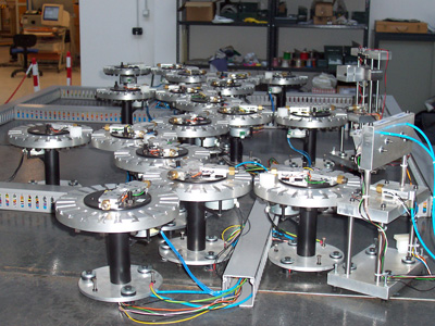
The ITIA-CNR mechatronic laboratory provides a suitable technology set-up that allows the control designer to experience all the phases of a control system design workflow within a collaborative learning infrastructure. Specifically, different simulation tools may be used to describe both the control strategies and the industrial processes by means of formal models. The verification of the control algorithms may be performed through closed-loop dynamic simulations in the development software environment, so eliminating major specification and design errors in the control algorithms. Afterwards, the translation of these algorithms into the industrial control code running on the target hardware is obtained automatically by selecting a specific target device, which has a tested control code from the functional point of view. Afterwards, the use of a small-scale plant characterized by the same input-output interfaces and discrete time dynamics of the real controlled factory (see Figure 2), allows the real-time control code to be verified through hardware in the loop simulation methodologies. Such tests allow the operational correctness of the automation software and the proper behaviour of electronic drivers to be verified, which also supports testing actions in non-nominal conditions such as possible failures that could happen on the real plant. Thus, before the control software download on the real industrial control devices, the control engineer is able to improve the control strategies without risking damage to industrial devices.
In this testbed set-up, different types of physical communication technology (ie different fieldbus solutions) may be tested and compared, thus evaluating the best-performing solution for a specific industrial automation need.
The ITIA-CNR automation lab also supports remote usage functionalities by means of Internet-based technology. A truly collaborative learning environment is thus available, in which different users may develop, test and compare automation solutions using the illustrated facilities.
The lab is also directly connected, via a real-time fieldbus, to the ITIA-CNR RTDI shoe factory. This factory, exploited for process and product innovation efforts, is a real production system that manufactures custom-made shoes. Thanks to this connection, the automation solutions developed within the automation lab can be directly applied and tested on the real factory as well.
These features of the ITIA-CNR remote collaborative laboratory and of the RTDI factory infrastructure illustrate the implementation of innovative teaching concepts. Education research and innovation systems have been integrated to provide a new means of technology-enhanced learning in the field of automation.
Please contact:
Emanuele Carpanzano and Andrea Cataldo
ITIA-CNR, Italy
E-mail: emanuele.carpanzano![]() itia.cnr.it, a.cataldo
itia.cnr.it, a.cataldo![]() itia.cnr.it
itia.cnr.it

