by Shaun de Witt, Richard Sinclair, Andrew Sansum and Michael Wilson
One driver for the data tsunami is social networking companies such as FacebookTM which generate terabytes of content. Facebook for instance, uploads three billion photos monthly for a total of 3,600 terabytes annually. The volume of social media is large, but not overwhelming. The data are generated by a lot of humans, but each is limited in their rate of data production. In contrast, large scientific facilities are another driver where the data are generated automatically.
In the 10 years to 2008, the largest current astronomical catalogue, the Sloane Digital Sky Survey, produced 25 terabytes of data from telescopes.
By 2014, it is anticipated that the Large Synoptic Survey Telescope will produce 20 terabytes each night. By the year 2019, The Square Kilometre Array radio telescope is planned to produce 50 terabytes of processed data per day , from a raw data rate of 7000 terabytes per second. The designs for systems to manage the data from these next generation scientific facilities are being based on the data management used for the largest current scientific facility: the CERN Large Hadron Collider.

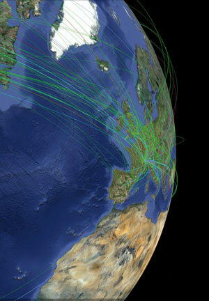
Figure 1: A snapshot of the monitor showing data analysis jobs being passed around the Worldwide LHC Computing Grid.
The Worldwide LHC Computing Grid has provided the first global solution to collecting and analyzing petabytes of scientific data. CERN produces data as the Tier0 site, which are distributed to 11 Tier1 sites around the world - including the GRIDPP Tier-1 at STFC’s Rutherford Appleton Laboratory (RAL) in the UK. The CASTOR storage infrastructure used at RAL was designed at CERN to meet the challenge of handling the high LHC data rates and volume using commodity hardware. CASTOR efficiently schedules placement of files across multiple storage devices, and is particularly efficient at managing tape access. The scientific metadata relating science to data-files is catalogued by each experiment centrally at CERN. The Tier1 sites operate databases which identify on which disk or tape the data-file is stored.
In science the priority is to capture the data, because if it’s not stored it may be lost, and the lost dataset may have been the one that would have lead to a Nobel Prize. Analysis is given secondary priority, since data can be analysed later, when it’s possible. Therefore the architecture that meets the user priorities is based on effective storage, with a batch scheduler responsible for choosing compute locations, moving data and scheduling jobs.
The data are made available to researchers who submit jobs to analyse datasets on Tier2 sites. They submit processing jobs to a batch processing scheduler that states which data to analyse, and what analysis to perform. The system schedules jobs for processing at the location that minimises data transfers. The scheduler will copy the data to the compute location before the analysis, but this transfer consumes considerable communication bandwidth, which reduces the response speed.
The Tier1 at RAL has 8PB of high bandwidth disk storage for frequently used data, in front of a tape robot with lower bandwidth, but a maximum capacity of 100PB for long term data archiving. In 2011, network rates between the Tier-1 and wide area network averaged 4.7Gb/s and peaked at over 20Gb/s; over 17PB of data was moved between the Tier-1 and other sites worldwide. Internally, over the same period, 5PB of data was moved between disk and tape and a further 28PB between disk and the batch farm. During intense periods of data reprocessing internal network rates exceeded 60Gb/s for many hours.
Storing and retrieving data is not that difficult - what’s hard is managing the data, so that users can find what they want, and get it when they want. The limiting factor for Tier1 sites is the performance of the databases. The RAL database stores a single 20 gigabyte table, representing the hierarchical file structure, which performs about 500 transactions per second across six clusters. In designing the service it is necessary to reduce to a practical level the number of disk operations to the data tables and the log required for error recovery on each cluster. Multiple clusters are used, but that introduces a communications delay between clusters to ensure the integrity of the database, due to the passing of data locking information between them. Either the disk i/o or the inter-cluster communication becomes the limiting factor.
In contrast, Facebook users require immediate interactive responses, so batch schedulers cannot be used. They use a waterfall architecture which, in February 2011, ran 4,000 instances of MySQL, but also required 9,000 instances of a database memory caching system to speed up performance.
Whatever the application, for large data volumes the problem remains how to model the data and its usage so that the storage system can be appropriately designed to support the users performance demands.
Please contact:
Michael Wilson, STFC, UK
Tel: +44 1235 446619
E-mail:


