


The conventional automotive industry is a market of mass production. On the one hand, due to the fact that the same platform may be used for different car generations, the lifecycle of a control network architecture (physical network and communication schedule) is expected to be at least one decade. On the other hand, future extensions to car functionality come along with increased bandwidth requirements. Additionally, there are safety requirements to fulfill that have to be reflected in the design of the control architecture. The technical challenge is the design of an architecture that fulfills existing requirements while being open for new functionalities without the necessity to re-design the whole control network.
This challenge is addressed by the DTF Data time flow simulator, a discrete-event simulation environment that will help to identify and validate an optimal car control architecture with regard to technical requirements, safety requirements and industrial norms. The idea is to derive the control architecture in an early design phase, ideally at the requirement specification stage, to build a simulation model of the architecture and to test the control network in the simulation environment. If the tests reveal requirement violations (eg deadlines of safety-relevant signals are missed), the control network is re-designed in the DTF simulation environment or the communication schedule is modified. This cycle is repeated until all requirements are met.
Figure 2 shows the structure of the DTF simulation environment. Starting with a graphical description of the system, the converter generates a textual bus model description that in turn is the input for the parser. The parser checks the bus model description for correctness and consistency and passes the model description to the DTF simulator engine.
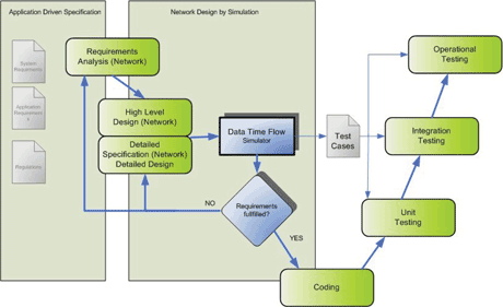
Figure 1: DTF development cycle.
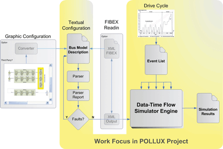
Figure 2: DTF simulation environment.
The simulator engine creates the necessary elements according to the model description. Then, the event list is generated according to the drive cycle description (an example for a drive cycle description is a sequence of events that defines different accelerator pedal positions for different points in time). Last, the event list processing is started with the first event. In the course of the simulation process, an event received at an element may lead to the creation of another event that is added to the event list. Simulation is complete when the event list is empty. All events are logged into a simulation results file that can be processed offline after simulation ends to gain data necessary for visualizations and for further analysis.
Principle of operation
The DTF principle of operation is to build up complex control systems from primitive building blocks (eg sensors, processors, actuators), the elements. Each element has an input buffer, a propagation delay and an action routine. Upon reception of a trigger, an element reads its input buffer, generates an output value according to its action routine, and transmits the output value with a defined propagation delay. Element triggers are event triggers (an event for this element is defined in the event list) or time triggers (the element triggers itself with a defined period). Each element has one or more inputs and one output. Elements can be grouped into super-elements, derived blocks with a high inner complexity which group logical functions belonging together into a single block (eg a Controller Area Network CAN bus). Signals are issued to the sensor elements and signal propagation is observed, both in the domains of value and time, from the sensors over the control network to the actuators. From the signal propagation time distribution over the control network important information can be gained about the dynamics and responsiveness of the system, especially for safety-relevant signals like the accelerator pedal position that are usually subjected to real-time constraints.
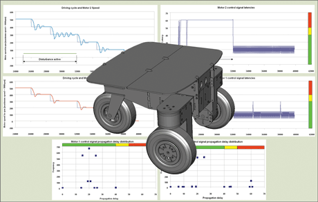
Figure 3: Concept Development Platform and DTF Simulation Results.
Validation
For validation of the DTF implementation a Concept Development Platform CDP is used to compare simulation results and bus measurements from the CDP. As shown in Figure 3, the CDP is a single-axe driving platform where each wheel is driven by one electric motor, stabilized by a free-running support wheel at the back. The CDP provides the mechanical system to develop automatic control software for the powertrain as well as the necessary structures for network design. The Data Time Flow Simulator DTF is currently under development at the Austrian Institute of Technology (AIT) in the context of the ARTEMIS Joint Undertaken (JU) POLLUX project that is related to the control electronics architecture design of the next generation of electric cars.
First simulation results are available and have been presented at the annual POLLUX project meeting in Brussels. The DTF simulator results were approved by the project partners and this tool is going to play an important role in simulation and assessment of vehicle control network systems.
Please contact:
Erwin Kristen
AIT Austrian Institute of Technology GmbH / AARIT, Austria
E-mail:
